Bonding With Masonry
Words: David Biggs
By David Biggs
This month’s questions come from an architect, a masonry contractor, and an engineer. What questions do you have? Send them to info@masonrymagazine.com, attention Technical Talk.
Q. An Architect writes that he is planning a vehicle maintenance facility of 142 ft x 80 ft that requires large openings for the vehicles? His Structural Engineer says she has to use steel moment frames to brace the building in the long direction due to the openings and the lack of shear walls.
The Owner wants a CMU building to avoid painting steel columns and congestion adjacent to the doors. The Architect asks is there a masonry-only solution for the exterior walls? A schematic of the building is shown in Figure 1.
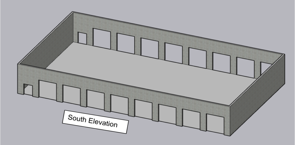 Figure 1 – Schematic building
A. Thank you, this is a very interesting question. But, there is a solution!
The east and west walls clearly provide sufficient shear wall to brace the north-south direction. However, the engineer’s concerns are for both the north and south walls which would both be bearing walls.
First, let’s discuss traditional masonry wall design. Walls are either loadbearing or non-loadbearing. For a one-story building, the walls span vertically between the foundation and the roof. Lateral loads are transferred into the roof diaphragm and onto the shear walls. addition, the building bracing is developed by utilizing the walls as shear walls.
Shear walls are necessary because the single wythe or cavity walls are generally too flexible to cantilever from the foundation and provide adequate stiffness against out-of-plane deflection (see Figure 2). However, diaphragm walls can be designed with much higher stiffness to resist out-of-plane loading as a cantilever.
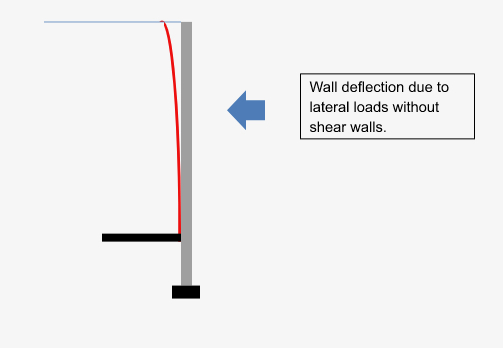 Figure 2 - Out-of-plane wall deflection
Diaphragm walls are explained in NCMA TEK 14-24, Design of Reinforced Concrete Masonry Diaphragm Walls and there is a worked-out example. Figure 3 shows a cross-section of one of these walls. The wall can be constructed with 6-inch and 8-inch units that are reinforced. The overall thickness varies ( twall) based upon the size of the cavity. The rib spacing is selected to allow the full wall to act compositely. While CMU is shown, reinforced clay masonry units can also be used.
Using diaphragm wall methodology, walls can be designed with very high stiffness due to the cellular configuration of the walls. So, the solution for this project is to design the east and west walls to accommodate the east-west lateral loads and act as cantilevers for east-west building loads. The roof structure would be a connector so the east and west walls interact to share the overall lateral loads. The north and south walls would not function as shear walls except for seismic self weight..
For north-south building loads, the north and south walls would be traditionally designed for out-of-plane loads to span to the roof diaphragm which would transfer those lateral loads to the east and west shear walls.
The internal void greatly reduces the volume of the masonry used in the wall in comparison to a solid wall, but the moment of inertia that controls stiffness is only reduced by approximately 15%.
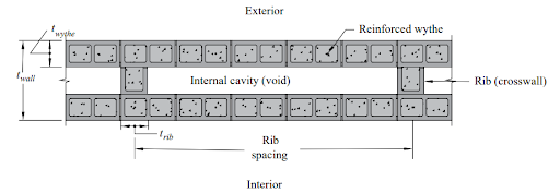 Figure 3 – Diaphragm wall (courtesy of NCMA)
Summary
- Diaphragm walls of reinforced CMU or clay masonry can be used in place of shear walls. They can be utilized only where needed structurally. Figure 4 shows a fire station with the diaphragm walls identified. The front and back walls are framed.
 Figure 4 – Fires station with diaphragm walls (courtesy of Malcolm Phipps)
- The roof diaphragm needs to designed and detailed to accommodate the walls.
- The stiffness of the diaphragm walls can be used for numerous large one-story structures such as movie theaters, aircraft hangers, industrial facilities and more.
Q. An Engineer is planning a project and wants to use through bolts with a reinforced CMU wall. She notes that TMS 402 only provides design criteria for embedded (one-sided) bolts and asks whether there is criteria for through bolts?
A. This question is usually answered by each engineer by using the “one-sided” anchor formulas provided TMS 402. These are modified by engineers to achieve what they perceive as a safe design.
A National Science Foundation research project on Hybrid Masonry (NEESR-CR: Hybrid Masonry Seismic Structural Systems) included testing for through bolts. This work was highlighted in a series of two articles by Gaur Johnson and Ian Robertson of the University of Hawaii (Hybrid Masonry Connections and Through-Bolts).
Figure 5 is taken from those articles and shows the failure modes considered in the research. The walls were considered unreinforced. Four of the modes were then compared to TMS 402 criteria while the fifth was compared to ACI 318.
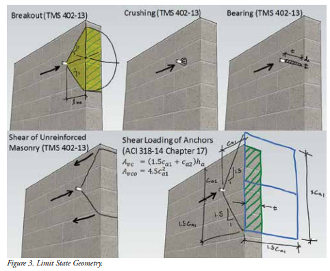 Figure 5 – Failure Modes of Through Bolts (courtesy of Structure magazine)
Figure 6 summarizes the results of the testing. Pcr is the first cracking value while Pu is the calculated nominal strength. A Pcr/Pu ratio of less than 1.0 indicates the calculated value is unconservative.
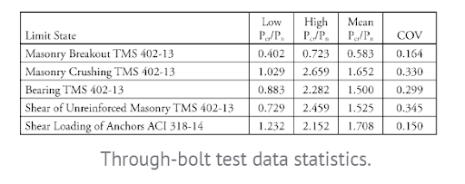 Figure 6 – Through-bolt test data statistics (courtesy of Structure magazine)
Summary
- Most engineers will use reinforcement in the masonry walls. The test values are conservative relative to breakout and edge shear.
- The testing was performed on a small sample of specimens and should not be taken as conclusive. However, if engineers are using TMS and ACI formulas, this work gives some data on through-bolt expected performance.
Q. A Mason Contractor has been asked by an Owner to reinforce an existing masonry cavity wall composed of brick veneer and CMU backup. The wall was built with no vertical reinforcement, but cracking has developed, and the Structural Engineer is proposing to insert vertical bars into the wall and grout them. After a few removals from the interior, the mason verifies that the CMU walls are unreinforced.
The mason asks if there are other options to lessen the cutting required to install the bars and the full grouting required.
A. Thank you for the question. The answer is provided using some photographs from an actual project with unreinforced CMU walls and a brick veneer ((courtesy of Walkowicz Consulting Engineers).
Figure 7 is an existing building that experienced horizontal cracking of the CMU backup. The site is low seismicity. The cracking was determined to be due to brick growth causing wall expansion and cracking the CMU.
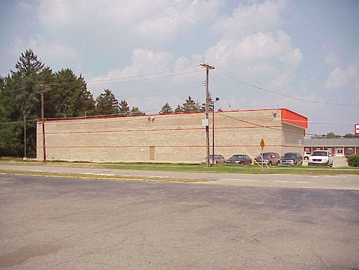 Figure 7 – Existing building with vertical wall cracks
The solution selected was to post-tension the CMU. Post-tensioning is a reinforcing technique that is included in Chapter 10, Prestressed Masonry of TMS 402-16, Building Code Requirements for Masonry Structures. It can be used whenever minimal grouting is desired.
Figure 8 shows the top of the wall. Reinforcing bars were used as tendons. Two top anchors are seen; the top course was grouted solid for bearing.
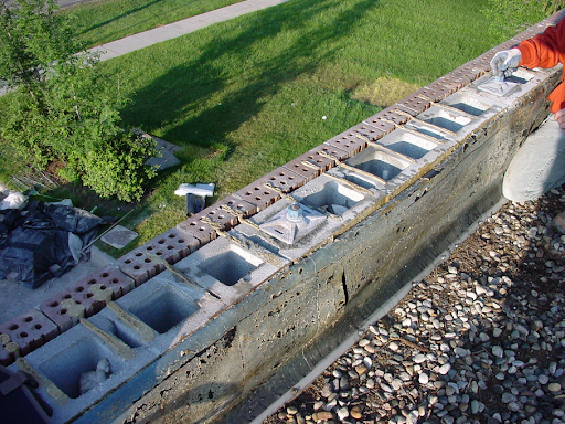 Figure 8 – Top of wall prestressed anchors
Rather than fully slotting the wall vertically, the tendons were installed in partial lengths. Figure 9 shows the wall prepared for the tendons and to provide a tendon restraint. Figure 10 is taken from a different project but illustrates how the tendons were connected by couplers.
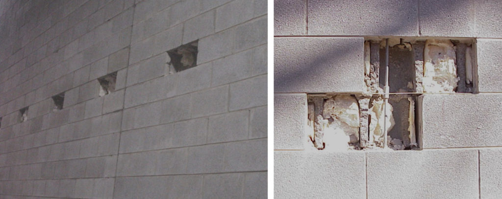 Figure 9 – Partial wall cutouts for tendons Figure 10 – Couplers for tendons
Figure 11 shows the cut-outs for the bottom of the wall. They are used as cleanouts, provide access to anchoring the tendon into the concrete foundation wall, and provide for the first coupler. The recommendation is to use high-strength non-shrink grout for setting the foundation anchors.
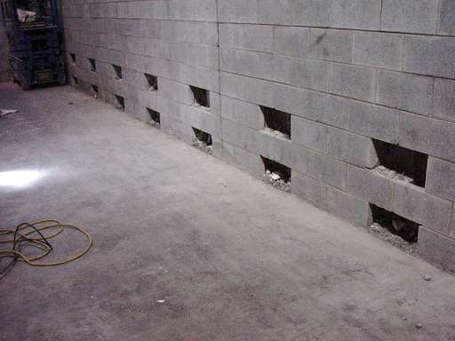 Figure 11 – Bottom of wall
Once the tendons are installed. The face shells of the CMU openings are infilled. No grouting was required for this design. Sometimes grout plugs are installed near the couplers to restrain the tendon from moving horizontally in the CMU cell. Finally, the tendons are tensioned from the top using a small jack.
Summary
- Post-tensioning offers opportunities to strengthen a wall and avoid significant grouting.
- Engineers should see TMS 402 for prestressed masonry. The Masonry Designer’s Guide from TMS has worked out examples.
Thank you again for following this column. Remember, by bonding we get stronger! Keep the questions coming. Send them and your comments to info@masonrymagazine.com, attention Technical Talk. If you’ve missed any of the previous articles, you can find them online for Bonding with Masonry at Masonry Design.
David is a PE and SE with Biggs Consulting Engineering, Saratoga Springs, NY, USA (www.biggsconsulting.net). He specializes in masonry design, historic preservation, forensic evaluations, and masonry product development.
Keywords for this issue: diaphragm walls, lateral support, through-bolts, post-tensioning, strengthening