Bonding with Masonry
Words: David Biggs
By David Biggs
This month’s questions come from engineers. What questions do you have? Send them to info@masonrymagazine.com, attention Technical Talk.
Q. An engineer writes that during the construction of a building, masonry bearing walls supporting a roof structure developed some cracking at the top bond beams. The roof structure includes LH10 and LH11 bar joists and metal deck; the deck had not yet been installed but the joists were welded to the bearing plates. The daylight temperatures were about 20 degrees F above normal when the cracking was noticed. What could be the cause? The photo shows the cracking.

Figure 1 – CMU cracking
- Thank you for the question! This is not a frequent problem, but it is also not unique. Thermal effects on the steel can have consequences for the masonry. You also indicated the wall is 8-inch CMU, partially grouted. The joists are offset on either side and each spans approximately 52 feet.
Figure 2 shows the design detail where we see that the second course is a continuous bond beam.
Figure 3 shows the joists recessed in the top course because the wall was not designed in coursing. The specifications required the CMU to be grouted solid under the bearing of the joist. The bearing plates are 6” x 6” x 3/8” with 2- ¾” diameter x 4” headed studs. The visible masonry cracking is emanating from the bearing plate in line with the headed studs.

Figure 2 – Design Detail

Figure 3 – Recessed bar joists
This is a case where the standards have no good advice. The available information may even be considered contradictory; let’s look.
- TMS 402, Section 1.2.1 requires the drawings provide:
- “(h) Provision for dimensional changes resulting from elastic deformation, creep, shrinkage, temperature, and moisture.”
No specific recommendations are provided, especially when the masonry interacts with other materials such as bar joists.
- The Steel Joist Institute’s Standard Specification for K-Series, LH-Series, And DLH-Series Open Web Steel Joists and for Joist Girders, Section 5.4.1 includes:
- “K-Series, LH-Series, DLH-Series Joist or Joist Girder end supported by masonry or concrete shall bear on steel bearing plates and shall be designed as steel bearing.”
- “The ends of LH-Series, DLH-Series Joists and Joist Girders shall extend a distance of not less than 6 inches (152 mm) over the face of masonry or concrete support unless it is deemed necessary to bear less than 6 inches (152 mm) over the support.”
- “K-Series, LH-Series, DLH-Series Joists and Joist Girders shall be anchored to the steel bearing plate”
- “If the steel bearing plate is located more than 1/2 inch (13 mm) from the face of the wall, or the minimum bearing over the masonry or concrete support cannot be provided….special consideration shall be given to the design of the steel bearing plate and the masonry or concrete by the specifying professional.”
- “The steel bearing plate width shall not be less than that shown in Table 5.4-2 perpendicular to the length of the joist. The plate is to be designed by the specifying professional and shall be furnished by other than the joist manufacturer.” For LH joists, Table 5.4-2 recommends a minimum bearing plate width of 9 inches. Although this is larger than what was specified, it is unlikely the cause of the cracking since the spacing between the studs could be only 3 inches wider apart.
From Section 5.7.1,
- “Ends of K-Series, LH-Series, and DLH-Series Joists and Joist Girders resting on steel bearing plates on masonry or structural concrete shall be attached thereto, as shown in Table 5.7-1, with a minimum of two fillet welds, or with two bolts, or the equivalent.”
So, what is expected?
- SJI requires anchorage by welding or bolting. TMS wants accommodation for thermal effects. The joist anchorage needs to accommodate uplift and provide bracing to the top of the wall.
In 1996, Masonry Construction magazine published “Masonry-to-steel-joist Connection” by Walter Laska (http://masonrytech.com/masonrytosteeljoist.pdf). This excellent article describes several issues with bar joists to masonry connections and is worth reading by design engineers. The author recommends a) provide a ¾-inch between the joist and the top of the wall to avoid rotation of the joist bearing on the face shells and causing cracking, and b) provide a special slip connection for the thermal movement that also allows the joists to brace the wall. No suggestions for a specific detail are provided. Providing slip to the anchorage that accommodates thermal effects on the masonry yet still braces the wall is easy to say and harder to achieve. If any reader has a solution, we invite your input!
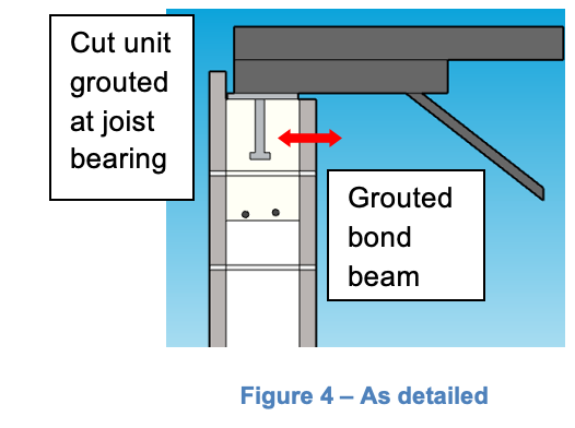
- The second option is to detail the top of the wall to be more robust to accommodate thermal effects. For this, we turn to the actual detail. As shown in Figure 2, the continuous bond beam is in the second course and the top course is cut and grouted under the bearing. The cut face shell is notched for the joist end. Also, note that the bearing plate studs are 4-inches long and don’t extend into the grouted bond beam (Figure 4). Horizontal forces on the bearing plate will transmit locally into the grout and the face shell and crack the unit.
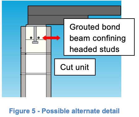
An alternative would be to engage the bearing plate studs with the continuous bond beam bars This might require increasing the length of the studs or moving the cut unit to the second course. (Figure 5). The continuous bars would then help confine the headed studs and distribute the horizontal forces along the bond beam to help mitigate the potential localized cracking.


MCAA also has a detail posted on its website (Figure 6). At the joist bearing, there is a continuous bulb tee embedded in the bond beam that provides continuity to distribute the horizontal loads along the length of the bond beam. The drawback may be that the tee portion needs to be sufficiently wide to bear the joist fully and the bulb needs to resist uplift.

Figure 6 – Wall Detail (courtesy of MCAA)
- A third option would be to use the alternate detailing in Figure 5 and also require the roof joists to be welded after the roof and insulation are installed. This will create some logistics to provide temporary wall bracing until the roof joists are tied in. But, it would mitigate some of the thermal effects on the wall during construction.
Summary:
- Accommodating thermal changes during construction is difficult due to the competing needs of the two materials, the steel bar joists and the masonry walls.
- Neither the steel industry nor the masonry industry currently has a standard detail to address the multiple needs.
- Engineers are advised to read the Laska article, consider the possible effects on the construction due to thermal changes, and create a design detail and specification that meets their design needs.
Q. Another engineer writes that his architect client is showing a narrow pier (2’-8”) between 12-foot openings (see Figure 7). The wall has 10 feet of single-wythe masonry above the openings. Using steel beams over the openings takes up a portion of the pier width with the bearings. How should the pier be designed?

Figure 7 – Overhead door with narrow pier
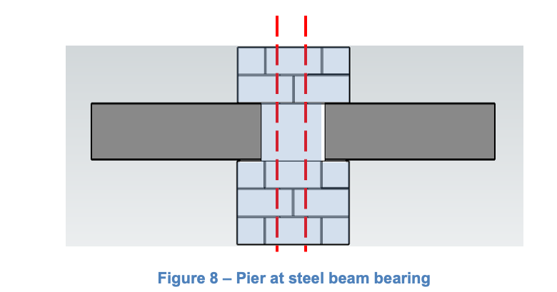
- You’ve brought up an issue that commonly occurs with steel beams over openings. Each beam bearing usually requires a 6-inch bearing plate. Figure 8 graphically shows the restricted pier due to the bearings. The 2’-8” pier has four cells but the beam bearings restrict two of them.
The courses are not shown for the beam depth for clarity. To avoid interference with the beams, only the two center cells can contain vertical bars.

To design the pier for out-of-plane loads, the effective pier width is only 16 inches at the level of the beams (see shading in Figure 8). The level of the beams is approximately at mid-height and close to the maximum moment region of the pier. Thus, this restricted width heavily influences the design.
For in-plane loads, the reduced width again limits the shear capacity of the pier to the point where it likely has no shear capacity.
Some additional thoughts regarding the use of steel beams over the openings:
- The masonry movement joints (EJ in Figure 7) adjacent to the openings limit the possibility of using the masonry over the opening as part of an in-plane wall frame for shear.
- The steel beam bearings should be detailed to account for the shrinkage effects through the joints.
- Flashing the steel beam is essential for single-wythe walls, especially through the movement joints.
- Anchoring “soaps” (partial width units acting as a veneer) to cover the steel beams is problematic. The masonry code requires anchored veneer units to be a minimum of 2-5/8” wide to accommodate mortar bedded anchors. Soaps are often only the width of face shells and therefore require a mechanical type of anchor to the steel beams.
- If this were a cavity wall, the structural issues would be the same for the pier design. However, the flashing of the steel beam and anchoring the veneer would vary slightly.
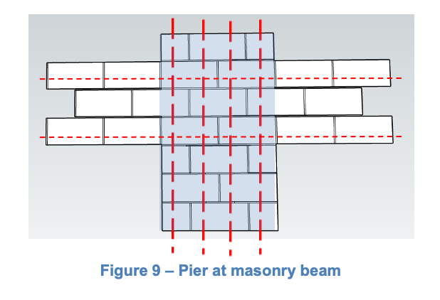
Consider using masonry beams to eliminate many of the problems associated with steel beams. Figure 9 shows that no restriction on the pier width exists (see vertical shading); all the pier cells can be used. Thus from a design perspective, the full pier width can be used for both out-of-plane and in-plane design.

The additional benefits of using a masonry beam are:
- The masonry beam can be integrated into the design of the wall above to create a wall frame for in-plane design.
- Flashing above the masonry beam for partially grouted walls is far simpler than flashing a steel beam.
- No soaps are necessary.
- Movements joints can reduced or eliminated using additional horizontal reinforcement in the wall above the openings using NCMA TEK 10-03 Control Joints for Concrete Masonry Walls – Alternative Engineered Method
Summary:
- Steel beams over single-wythe masonry openings create some unique challenges that affect the design of the piers supporting them.
- Flashing and anchoring “soaps” to steel beams can create constructability issues.
- Using masonry beams over openings mitigates some of the problems encountered with steel beams.
Thank you again for following this column. Remember, by bonding, we get stronger! Keep the questions coming. Send them and your comments to info@masonrymagazine.com, attention Technical Talk. If you’ve missed any of the previous articles, you can find them online in the archives of Masonry Design (http://www.masonrydesignmagazine.com/digital-editions/) starting with the Spring 2018 edition.
Keywords this issue: Bar joist bearing, cracked bond beam, thermal, steel beams, masonry piers, masonry beams
David is a PE and SE with Biggs Consulting Engineering, Saratoga Springs, NY, USA (www.biggsconsulting.net) and is also an Honorary Associate professor for the University of Auckland, New Zealand. He specializes in masonry design, historic preservation, forensic evaluations, and masonry product development.