In this month’s article we will take a closer look at ways of installing these products but first let us review what a rainscreen wall design is. Think of a rainscreen wall design like your car engine. For your engine to work correctly there needs to be an intake and an exhaust. The same rules apply to rainscreen wall designs. These wall systems need to not only drain, but also dry. The rainscreen wall design allows air to flow in a convective fashion within the wall from the bottom to the top, which reduces excess moisture that otherwise could be trapped within the wall system. This convective airflow helps prolong the life of all wall components involved.
Exhibit A shows the natural progression of airflow through a rainscreen wall assembly. This convective airflow neutralizes the air pressure between the outside environment and the inner wall. This pressure neutralization helps control the amount of moisture that can enter the wall structure.
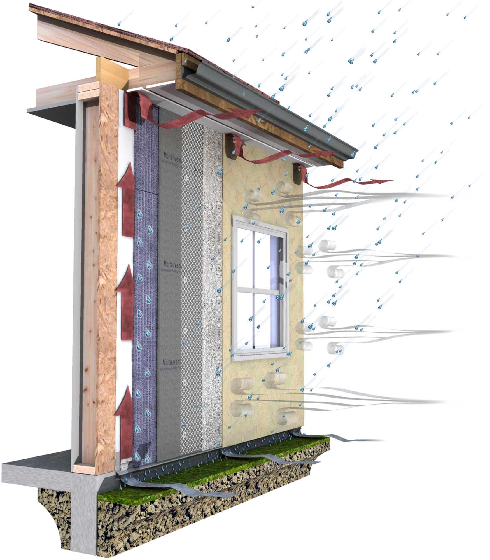 Exhibit A
So, why is 5mm the code requirement per the 2021 and 2024 IRC & IBC? The surface tension of moisture can span up to two-millimeters, so anything under two-millimeters could pose a problem for proper drainage in masonry cladding applications. For convective airflow, we recommend the capillary break be no less than four and a half millimeters, which is what brings us to 5mm. Remember the goal is to let in air for wall pressure neutralization, yet moisture travels through the air. The wider the airspace, the longer it will take for wall pressure neutralization and the more potential moisture we would allow into the wall system.
Now in multi-story commercial buildings, the same rules apply; however, these wall systems are often designed with their intake and exhaust at each floor level due to shelf angle installation and fire blocking. The airspace minimum in commercial cavity walls for example is one inch. It is not recommended to have a capillary break over one inch for a rainscreen wall assembly. Why? Because anytime an airspace is created a chimney effect could also be created. If a fire were to take place on the first floor of a building, science experts have determined a capillary break of one inch or less will not allow enough oxygen for flames to propagate.
The following details are not intended to be to scale, but to show the order of proper installation for the various wall components.
Exhibit B shows the base of a stucco wall. When using absorptive materials, such as stucco, it is recommended to have a minimum four-inch clearance from the ground. This will reduce the risk of moisture intrusion from ground soil or backsplash. Often, we see cladding installed to grade for aesthetic reasons. This is not recommended, especially with absorptive cladding materials.
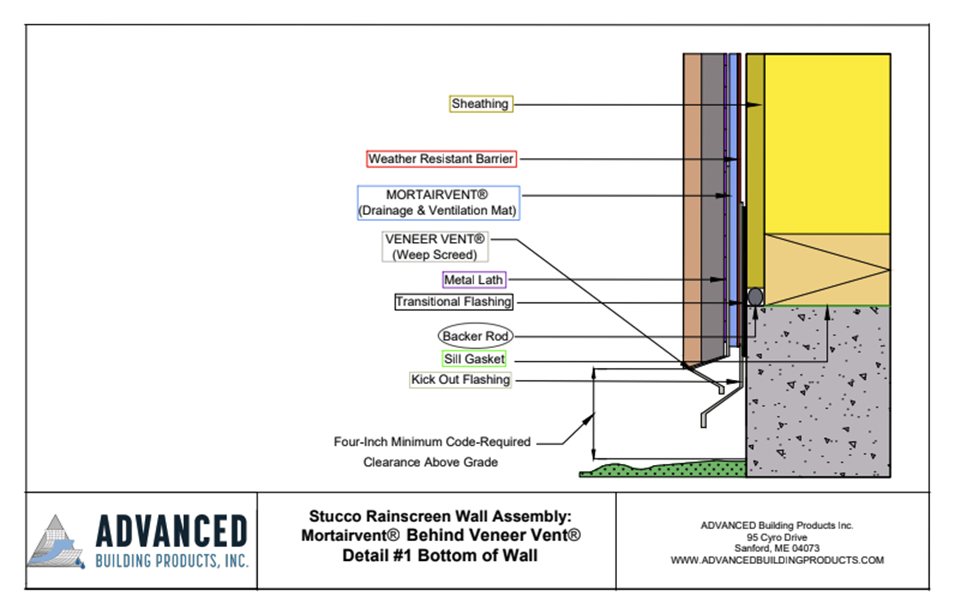 Exhibit B
I have seen projects that start with sheathing attached to the studs and the weather resistant barrier then placed across the surface area of the sheathing. Often transitional flashings and kickout flashing are not installed. A better approach is again seen here in
Exhibit B. One thing to note about this detail. Your weep screed should have drainage channels located on the underside of the weep screed for proper moisture evacuation.
Exhibit C is a newer wall design that is gaining popularity. This wall system includes outboard rigid insulation. Where should the drainage and ventilation mat go in this situation? In front or behind the rigid insulation? Well, that all depends on your goal. Protecting the structural shell of the building is always a top priority. In this case, install the drainage and ventilation mat behind the rigid insulation as shown here. If the rigid insulation is non-permeable and the seams of the rigid insulation are taped correctly and the base flashings are installed correctly, this design is a good option. With the use of outboard rigid insulation, the designer needs to pay close attention to the top ventilation design. There are products available to create the necessary top ventilation; however, check to see if these pieces have been designed to accommodate one-inch outboard rigid insulation.
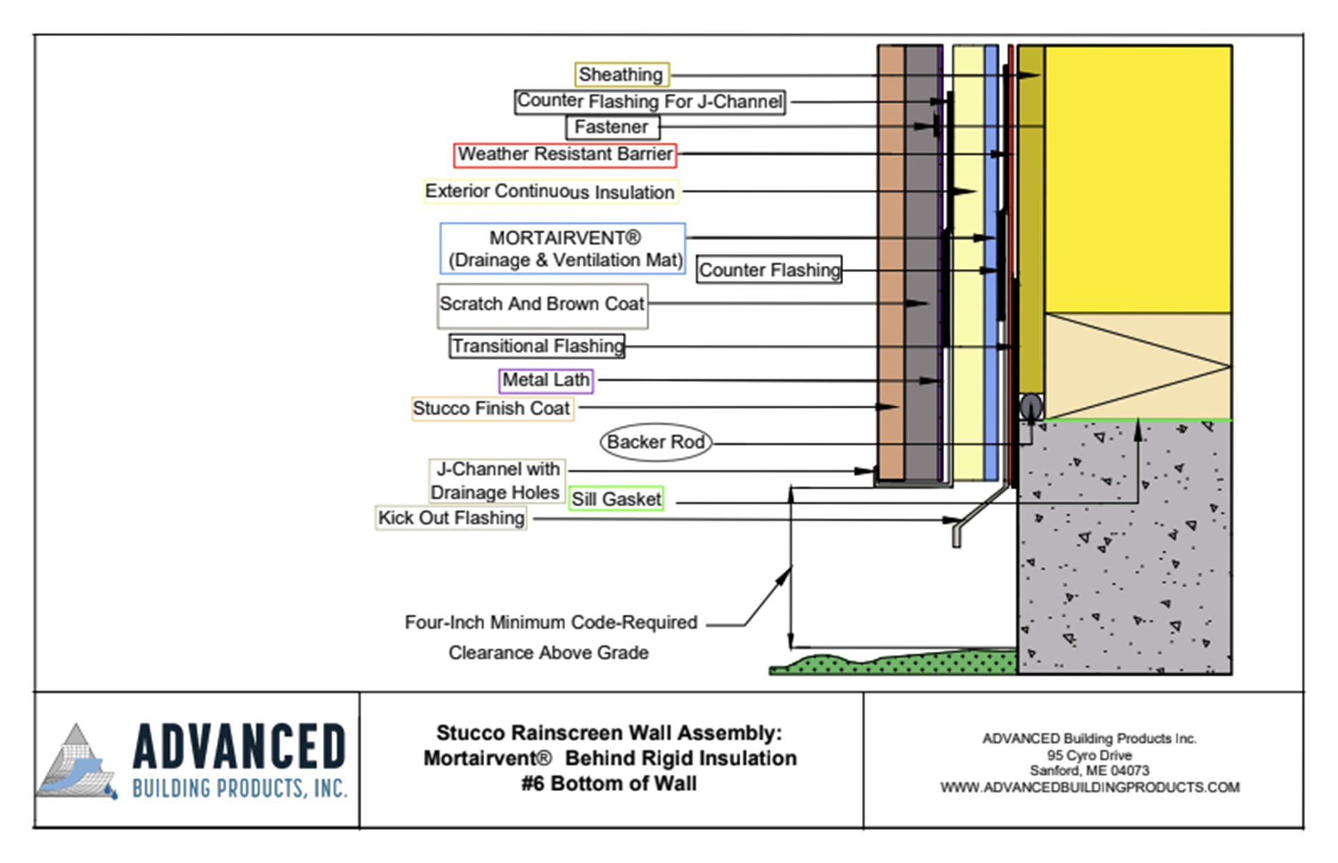 Exhibit C
Another train of thought is to ask yourself where will most moisture enter a wall system? From the outside.
Exhibit D is a favorable solution. Notice the drainage & ventilation mat is installed on the outside of the rigid foam insulation. This will reduce the damaging effects that otherwise could harm the cladding. If detailed correctly, we already know the rigid insulation will have its seams taped correctly and the weather resistant barrier will be installed and any damage caused during installation will be fixed. In this detail it is recommended that a vapor permeable drainable weather resistant barrier be installed in place of a standard house wrap to better manage any vapor drive from the inside of the structure moving outwards. The drainable weather resistant barrier should not encounter the masonry scratch coat, since it is behind the rigid insulation. The opportunity for better drainage compared to a standard weather resistant barrier exists. Just to clarify, a drainable weather resistant barrier, also referred to as a drainable house wrap, cannot take the place of a drainage & ventilation mat. Why? Remember that moisture can span one to two millimeters. Drainable house wraps are within one to two millimeters. Their 90% drainage efficiency (to meet code) can be compromised in masonry cladding applications due to scratch coat installation practices.
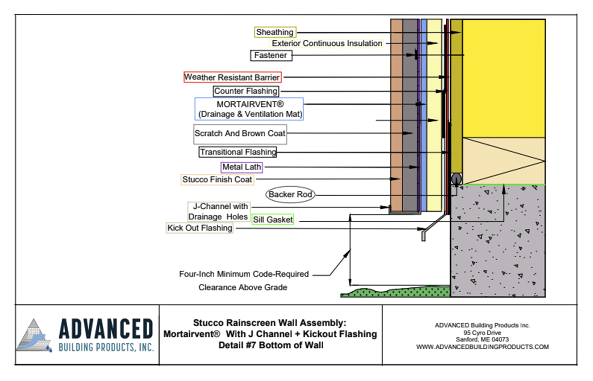 Exhibit D
Another advantage to rainscreen wall designs in commercial applications is shown below in
Exhibits E. With thicker outboard rigid foam being specified, along with an industry average two-inch airspace or more, these masonry walls are getting thicker. They are also getting more expensive. The wider the wall, the wider the through wall flashing. Wall tie tolerances and designs need to be considered. The overall footprint of the building becomes larger. By utilizing an all-wall drainage and ventilation mat
Exhibit F, builders can successfully build utilizing the one inch minimum airspace required by code giving this wall design the ability to drain and dry as intended.
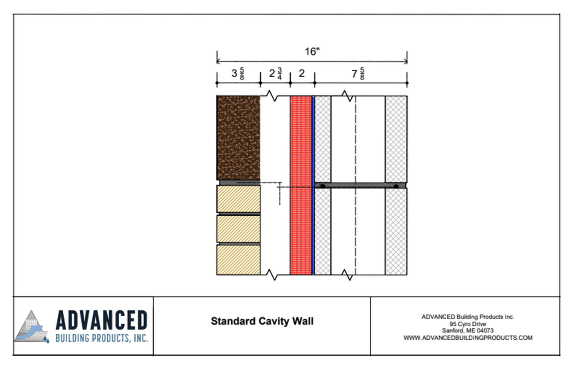 Exhibit E
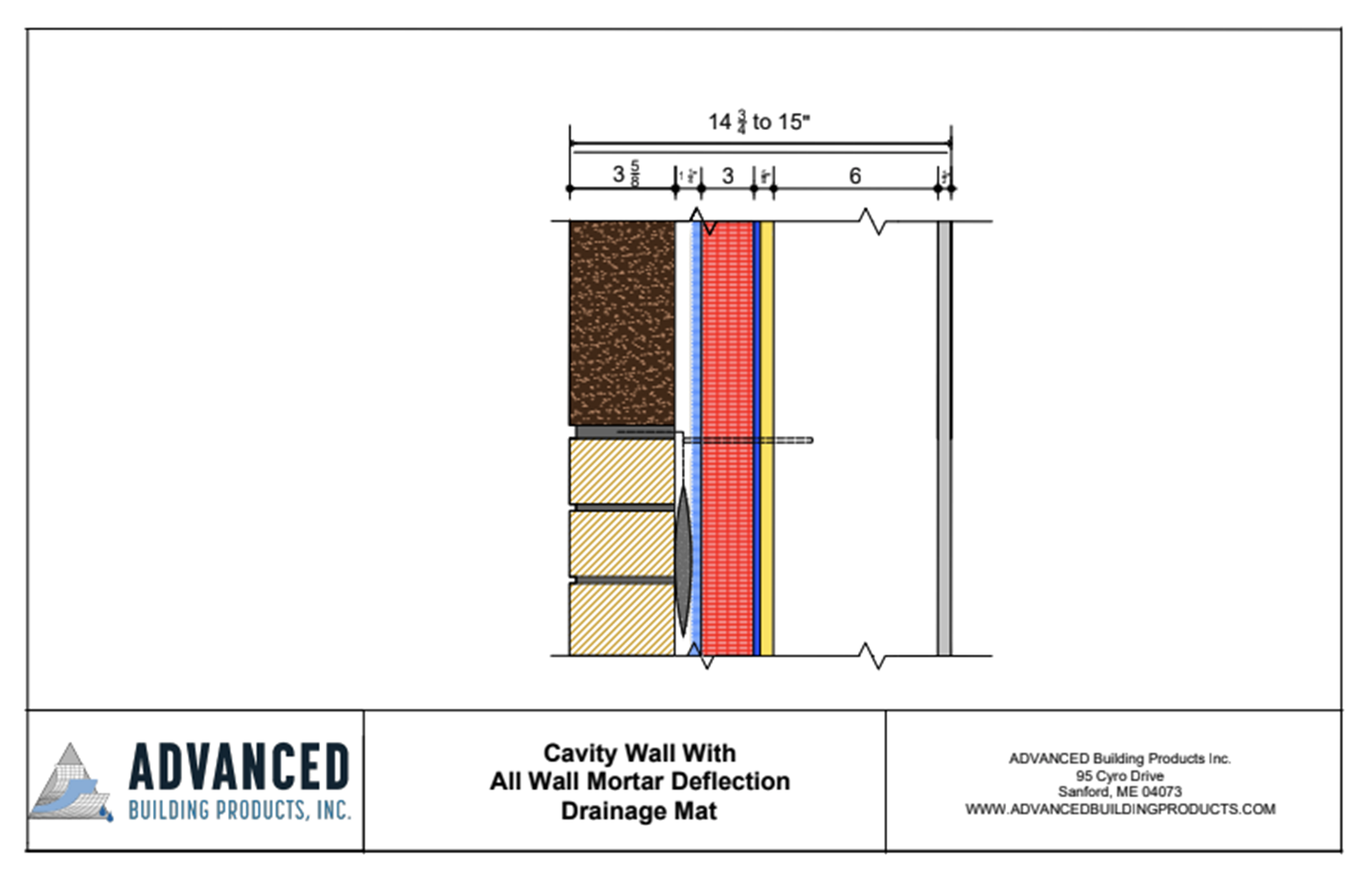 Exhibit F